Solid-State Tesla Coil
An article about Plauson’s invention: a system that will deliver current that can be used for industrial purposes.
Wield the power of lightning with this modern design that would make Nikola himself proud
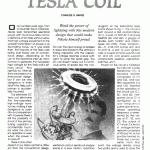
One hundred years ago, from a mountain top in Colorado, Nikola Testa transmitted electrical power with his famous Tesla coii for a distance of 25 miles without wires. That high voltage experiment in the wireless transmission of power is as fascinating today as it was back then. The majority of the Tesla coils being built today are of conventional design, depending on the use of line-operated step-up transformers to generate the necessary high voltage for the Tesla coil’s primary circuit. And i^^^smms^ rightfully so. After all, § they are based on a I time-proven design, 1 but it can be very I dangerous or even |Wield the power of lightning with this modern design that would make Nikola himself proud.
One hundred years ago, from a mountain top in Colorado, Nikola Testa transmitted electrical power with his famous Tesla coii for a distance of 25 miles without wires. That high voltage experiment in the wireless transmission of power is as fascinating today as it was back then. The majority of the Tesla coils being built today are of conventional design, depending on the use of line-operated step-up transformers to generate the necessary high voltage for the Tesla coil’s primary circuit. And i^^^smms^ rightfully so. After all, § they are based on a I time-proven design, 1 but it can be very I dangerous or even fatal if the Tesla coil’s primary is accidentally touched!
Our solid-state DC Tesla coil eliminates the Sine-operated, § high-voltage transformer, making it less dangerous to oper- § ate and experiment 1 with. However, there’s still the possibility of shock if the primary f tuning capacitor is s accidentally touch- ed while the circuit is in operation or even % when the power is 1 turned off.
There is one other aspect of our Tesla coii that is different from the conventional design, and that’s the DC part, in a standard coii design, the maximum spark length obtained from the secondary coii is primarily determined, in an efficient system, by the ACinput power to the Tesla system. In a DC coii, the input energy Is applied in steps and stored in the primar/’s tuning capacitor until the capacitor’s voltage reaches a level sufficient to jump the spark gap. The DC coil doesn’t spew out a continuous spray of sparks like the conconventional coii but sends out snappy sparks In a slow motion, machinegun like manner. Our DC Tesia coii only consumes a few watts of power but can output a 6- to 8- inch spark to ground.
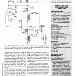
About the Circuit. The schematic diagram of the Solid-State Tesla Coil is shown in Fig. 1, The circuit is built around a 555 oscillator/tinner (IC1); a pair of SRF9130 P-channel HexFETs (Ql and Q2); a gaggie of diodes, both 1N4007 and 1N5401 types (D1-D94); three transformers— Tl, a 25-VCT, 2-amp unit, and T2 and T3, a pair of auto ignition coils; a couple of hand-wound coils (LI and 12); and several support components (resistors, capacitors, switches, etc.).
Power for the circuit is furnished by a 25-volt, 2-amp transformer (Tl), a full-wave rectifier (comprised of Dl and D2), and two fitter capacitors (CA and C5). Essentia! to the operation of the circuit are IC1, Q l , and Q2. integrated circuit iC 1 is configured as a low – frequency pulse-generator, whose operating frequency is determined by the values of R1, R2, and C2. The output of IC1 at pin 3 is fed to a voltage-divider |^» network comprised | L of R3 and R4, at the 1 | » junction formea by 11?-; those two components, From that point, the voltage divides along two paths and is used to drive the two P-channel HexFETs (Ql and Q2). The pulsing output of IC1 causes the HexFETs to turn on and off in unison. As the HexFETs—which operate like heavy-duty toggle switches—alternate between full conduction and cutoff, a series of voltage spikes is sent to a pair of auto ignition coils (T2 and T3), producing a relatively high instantaneous peak voltage across the primaries of T2 and T3. The rising and collapsing voltage across the primaries of the ignition coils causes a very high pulsating voltage to be induced into the secondaries of T2 and T3.
The output of each ignition coil (at its secondary winding) is fed through identical diode stringseach comprised of 45 series-connected 1-amp, 1Q0Q-PIV silicon diodes (D5 through D49 for Ql and D50 through D94 for Q2)—to a summing node at the junction of D49 and D94. The summed voltage causes C3 (the primary tuning and energy-storage capacitor, which is tied to the summing junction) to begin charging. The high DC voltage that’s stored In C3 is fed through a series of spark gaps to supply an oscillating source of energy to the primary coil of the Tesla system, LI.
Inductor LI is tuned to the natural resonance frequency of the secondary coil (L2) by adjusting the inductance of LI via a movable tap. Adjusting the primary coil to the nafurai resonance frequency of the secondary coil is the secret to any successful Tesla coil system.
Construction. The author’s prototype of the Solid-State Tesla Coil was put together as several subassemblies— perfboard (which contains the majority of the electronic components), driver, spark-gap, pancake-coil (LI, the primary coil), tower-coil (L2, the secondary coll), tuning/energy-storage assembly (C3), and a high-voltage-rectifier assembly. The majority of the subassemblies were then mounted to a round—15-inch diameter by 1- inch thick—baseboard, cut from pineboard stock.
Begin by cutting the pine-board stock to the required dimension. After cutting the pine-boord stock, a 2-inch PVC end cap was mounted open-end up to the center of the round baseboard. Thetwo ignition coils were then mounted to the baseboard using a pair of L-brackets; plumber’s tape can be used to secure the L brackets to the ignition coils. Or, if you prefer, large screwtype hose clamps can be used to secure the L-brackets to their respective ignition coiis. After securing the ignition coils in position, mount T1 to the baseboard.
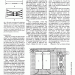
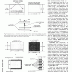
Next prepare the perfboard assembly, In the author’s prototype, the perfboard assembly, which measures 3’A x 5 inches, contains ail of the electronic components, except T1-T3, Q l , Q2, Fl, SI, D3-D94, and the remaining hlgh-voitage components. Interconnections between the various perfboard components were accomplished through pointto- point wiring techniques in typical breadboard fashion. Note: Although not really necessary, ICI was mounted to a small printed-circuit board, measuring 1 x PA inches, which was then mounted to the perfboard and wired Into the circuit. A template for that simple foi! pattern is shown in Fig, 2A, and the corresponding parts-placement diagram is shown in Fig. 2B.
Whether or not you decide to use that foil pattern, assemble the electronic portion of the circuit on the perfboard, guided by the schematic diagram (Fig. 1). A general layout for the Solid-State Tesla Coil’s perfboard assembly—on which R1-R4, C I , C2, C3,C5, D l , D2, and ICI (with or without printed-circuit board) are mounted—is shown in Fig. 3. Note that although C2—a 0.44-fiF capacitor-—is shown as a single component, it is actually a pair of parallel-connected 0.22-nF units.
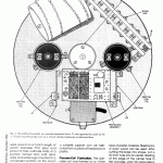
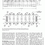
Once completed, check the board for construction errors, and if ali seems OK, mount the perfboard assembly to the baseboard. The perfboard assembly was mounted above T1, supported by a pair of 23/4- x 1 Vr-inch wood blocks, as illustrated In Fig. 4. When that’s completed, prepare the driver assembly.
The driver assembly is comprised of the two HexFETs (Ql and Q2) and a pair of diodes (D3 and D4) mounted to individual heatsinks that were fabricated from two 3’Ax 4-inch pieces of ,062-inch aluminum. Diodes D3 and D4 were mounted directly connected across the source and drain terminals of the HexFETs on the opposite sides of their respective heatsinks. On completion of the driver assembly, check your work for construction errors. If ali seems OK, mount the two HexFET/diode-mounted heatsinks to the baseboard on either side of the perfboard assembly, as shown in Fig. 4.
What remains are the pancakecoii assembly (LI), the tower-coil assembly (L2), the tuning and energy storage assembly (which revolves around C3), the series sparkgap assembly, and the high-voltage- rectifier assembly (comprised of D5-D94). Those assemblies, which were fabricated from readily available parts and materials, can be assembled in any sequence desired. But, iet’s start with the simplest item—the dual high-voltagerectifier strings. Begin the next phase of construction by cutting the leads of the ninety 1N4007 diodes to a length of /-inch. After cutting the leads, solder the diodes together anode-to-cathode to form two 46-diode strings (with a total length of about 22-inches)—one for each transformer output. (The overail string length isn’t critical so anything close will do.)
Afterward, the two diode strings were wound on a 5-inch length of 4-inch diameter PVC pipe and joined at their cathode ends at a junction formed from 6-32 hardware and solder lugs mounted to a convenient location on the 4-inch PVC pipe (see Fig, 4). Hot-melt glue was then used to hoid everything in place. The diode assembly was then mounted to the baseboard atop a 2-inch porcelain insulator. If a porcelain insulator isn’t available. a suitable support can be fashioned from a piece of hardwood or plastic.
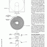
Pancake-coli Fabrication. The pancake coil was formed on a ‘/.-inch thick piece of Plexiglas material (which serves as a base and provides support for the primary) that was cut into a 12-inch diameter circle (see Fig. 5). If Plexiglas Isn’t readily available, just about any other type of plastic material, flberboard, or even wood can be used. After cutting the base into shape, cut a 4’A-inch hole into its center. Starting at the edge of the center hole in the coll base, wind 10V< turns (about 24 feet) of number 6 bare copper wire onto the base to form LI. The lOfl turns of LI should be spaced to evenly cover the coil’s Plexiglas form.
Note: If number 6 copper wire Isn’t available, any copper wire close in size will do (but, remember, bigger is better because current flows in the outer surface of the wire in a Teslo system). Don’t be too concerned if the coil doesn’t turn out picture perfect; winding the primary coil can be the most challenging part of building the Tesla coil, When finished, secure the coil in place with epoxy or hot glue. Drill a hole in the Plexiglas base at the end of the Inside turn and mount a banana jack for the ground end of LI and L2. Connect the end of the Inside winding to the banana jack and connect an 8- inch length of test lead wire to the jack and a banana plug to the other end.
After that, epoxy or hot giue a 4- Inch PVC end cap to the center of the primary coil’s base. The open rim of the end cap should be flush with the top of the Plexiglas base. Drill a hole in the center of the end cap large enough to clear a number 8-32 screw, Then using the same bit, drill a hole in the center of a 2- inch PVC end cap and bolt the two- and four-inch end caps together.
If the end caps are rounded on top, fill the gap where the two caps meet with epoxy or hot glue. The glue acts as a filler and adds to the stability of the coil support stand. Cut an 8-inch length of 2-inch PVC tubing. The 8-inch tube serves as a support for the two coils (LI and L2) in the final assembly,
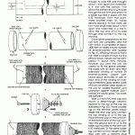
Tower-coli Fabricates. The tower (or secondary) coll, L2, was wound on a piece of PVC pipe, Figure 6 gives details of fabricating the tower-coil assembly. Begin by cutting the a section of 4-inch diameter PVC pipe to a length of I8Y2- inches (as shown In Fig, 6A). Then, temporarily place end caps on each end of the coil form (as shown in Fig. 6B) to make sure they fit snugly. Once the fit is confirmed, remove the end caps and then (again referring to Fig. 6B) drill a hole in the coil form of sufficient size to accommodate a 6-32 screw, about fi inch up from the bottom of the form. That hole is to serve as a tie point for the ground end of L2.
Next, drlli another hole about 1/2-inch off to the side of that hole just large enough for a test-lead wire to pass through, Make a mark one- Inch up from the bottom of the coil and In line with the first hole, Driil two very small holes (just large enough to pass #28 wire through) about ‘A Inch apart and horizontally In line with the bottom. That allows the bottom end of L2 to pass through the coll form and attach to a solder lug held in place with the 6-32 hardware, From that point, make another mark 16V: Inches directly above It. At that mark, drill two more small holes about ‘/.-inch apart and horizontally In a line to allow the top end of L2 to pass through and connect to the top terminal.
Once all the preparations for the coil form are complete, wind the coil—which Is comprised of about 1400 feet of neatly wound number 28 enamel-coated wire—guided by Fig, 6C. Winding the coll by hand can take a couple of hours, but if a lathe is handy, the job can be completed In about thirty minutes. However you wind the coil, be careful to fill the space between the marks with an even and neat solenoldal winding of number 28 enamel-covered copper wire. Leave about six-Inches of wire at each end of the winding for making connections. Spray several coats of Krylon (or similar) clear acrylic on the coil for added insulation and protection against moisture. Don’t overdo the acrylic spray: Two coats are sufficient.
Take a 4-inch PVC end cap and mount a feed-through ceramic insulator to the top of the cap (as illustrated In Fig. 6D), Place a solder lug on the terminal (screw head) Inside the end cap and connect the top winding of L2 to the lug. Place the end cap on the coil form. At the bottom end of the coil, connect the ground end of L2 to the solder lug mounted to the form with 6-32 hardware. To the same solder lug, connect a 3-Inch length of testlead wire with a banana plug attached. The plug goes into the banana jack that’s mounted on LI’s base to tie L2’s bottom winding to circuit ground. Figure 6E shows how the coil should look when completed.
Building the Capacitor. Capacitor C3 is a homemade unit comprised of 33 sheets of aluminum flashing and 34 sheets of plastic material sandwiched between a couple of pieces of pine board (which well hereafter refer to as a clamp)
Begin this phase of construction by manufacturing the capacitor clamp. The capacitor clamp is comprised of a pair of 15 x ]}’•/,- Inch end pieces cut from 2-inch thick length of pine wood, a 13’/:- x 11% -inch piece of Ve-inch thick fiber board, and two 8-inch x % – inch carriage bolts (see Fig. 7 for details). After cutting the pine and fiber boards to the dimensions indicated in Fig. 7 and drilling holes as required, glue the fiber board section to the bottom of the capacitor clamp, as shown. When the clamp is ready, prepare the capacitor’s dielectric and electrical plates.
The eiectrical plates for the capacitor were fabricated from a roll of 14-inch wide aluminum flashing, although aluminum foil can also be used. Figure 8A shows construction details for the plate (aluminum) section of C3. Start by cutting 33 sheets of flashing to 10 x 14 inches. After that, prepare the capacitor’s dielectric. The dielectric (see Fig. 8B) is comprised of 34 sheets of 0.06-Inch thick polyethylene material cut to 11 x 13-inches. Other types of plastic materials can also be used as the dielectric, as long as their insulating properties are sufficient to withstand the applied voltage. Note: Glass is not a suitable substitute.
Assemble the capacitor by placing one of the plastic sheets on the base of the clamp board, Position the first aluminum sheet, as shown in Fig. 8C, over the plastic sheet with a Vs-inch border on three sides, as Illustrated. Place another plastic sheet over the aluminum sheet and position the second aluminum plate over that sheet of plastic facing out the opposite side with the same ‘/2-inch border. Continue the process until all materials are used. When finished, there should be 17 sheets of aluminum facing OUT one side and 16 facing out the other side.
Place the top clamp board in position and tighten the two nuts until all of the plates are flat. The aluminum plates on each side of the capacitor are then bolted together in several sections. To that end, punch or drill holes through 3 to 4 of the protruding aluminum tabs sticking out each side and ciamp them together with 6-32 hardware and a solder lug, When all aluminum tabs are clamped in sections, tie all of the sections on one side together; then repeat the procedure on the other side (as indicated in Fig. 8D). The capacitor can then be hard wired to the circuit or connected with clip leads.
The Spark Gap. The spark gap for the Solid-State Tesla Coil is actually a multi-stage, spark-gap (multigap) arrangement, in which seven gaps are connected in series to ailow maximum gap adjustment. The multi-gap arrangement is comprised of two pieces of fiber board, and 16 bolts and nuts. Details for fabricating the multi-stage spark gap are given in Fig, 9, Fabricate the muiti-gap assembly by first cutting two pieces of 3A-inch fiberboard to 8’A x 2 inches, and drilling two ‘A-inch (0.250) holes in each end of each board (see Fig. 9A). Follow that by drilling the remaining seven holes in the two boards using a 0.201-diameter drill bit; tap each of the seven holes with a ‘A-20 tap. Screw all 14 (seven in each side) 1-inch ‘A-20 bolts into place. Make sure each bolt is screwed ali of the way in the board up to its shoulder. Connect the gaps together in series with jumpers as shown in Fig. 9B. Assemble the two halves with two, 2-inch ‘A-20 bolts and matching nuts. Place two compression springs over each bolt and place the other half of the gap assembly into position, Add the two outside adjustment nuts, set each gap to about 20 to 30 thousandths of an inch. Then attach the multi-gap assembly to the baseboard with two “L” brackets (refer back to Fig. 4). There is one final item to be added to the Tesia Coil—a toploading capacitor—which helps to increase the output voltage and spark length considerably. The toploading capacitor was constructed from four 6-inch-diameter galvanized adjustable (stovepipe) elbows connected together in a circle. Stovepipe elbows can be purchased at almost any large hardware- type store. After fabricating the top-loading capacitor, a metal strap is mounted to the unit and a hole drilled in the center, allowing it to be mounted atop L2.
Putting It All Together. Only operate the Tesla Coil when it is plugged into a grounded outlet! To do otherwise will result In poor performance and most likely cause shocks to the operator when touching the off/on switch. Set the 8-inch length of 2-inch PVC pipe in the end cap mounted on the wood base. Set the LI assembly on the pipe, and position L2 in place in the 4-inch end cap located in the middle of Ll. Plug L2’s ground into the jack on Li’s base and connect that ground to circuit ground, Hook the capacitor up and attach the lead from the spark gap to one turn in from the outside turn of Ll. Connect the output from the high voltage rectifiers and C3 to the spark gap Including all seven gaps in series. Place the top loading capacitor on L2 with washers and holding nut, Check all of the connections between all major components against the schematic drawing in Fig. 1, If everything looks good, turn the power on and the spark gap should become active, Take a long clip lead and connect one end to circuit ground and clip the other end to a wooden yardstick. Bring that end near one side of the loading capacitor. Sparks will jump to the lead at a distance of 6 to 8 inches.
If not, the circuit probably needs to be tuned. Turn the power off and discharge C3. Move the lead on Ll in about fi turn and repeat the experiment. If the spark output increases, go another half turn in and see what happens. If the spark decreases, then go back half turn and check again. Keep experimenting with the tap location until the best output is obtained, The spark gap controls the amount of voltage reached across C3 before discharge and the maximum output spark. If the gaps are set too close, the discharge output will be much less In length but more often in occurrence. With the multi-series gap arrangement, experimenting with various gap settings is easy.
The best place to view the Tesla Coil’s “fireworks” is in a darkened room. Hold one end of a fluorescent tube and bring it near the operating coil, If the coil is operating properly, the lamp should light with each discharge at two or three feet away from the coil, A clear incandescent lamp positioned close to i_2 will produce a beautiful blue and yeiiow lightning array from the lamp’s filament to the outer edge of the glass envelope. Just keep in mind that the voltage across C3 can hurt you, so be sure to discharge it before making any adjustments to the circuit. When not using the coil place a jumper lead across C3 as a safety measure, Good sparks always! fatal if the Tesla coil’s primary is accidentally touched!
Our solid-state DC Tesla coil eliminates the Sine-operated, § high-voltage trans- ; former, making it less dangerous to oper- § ate and experiment 1 with. However, there’s still the possibility of shock if the primary f tuning capacitor is s accidentally touch- ed while the circuit is in operation or even % when the power is 1 turned off.
There is one other aspect of our Tesla coii that is different from the conventional design, and that’s the DC part, in a standard coii design, the maximum spark length obtained from the secondary coii is primarily determined, in an efficient system, by the ACinput power to the Tesla system. In a DC coii, the input energy Is applied in steps and stored in the primar/’s tuning capacitor until the capacitor’s voltage reaches a level sufficient to jump the spark gap. The DC coil doesn’t spew out a continuous spray of sparks like the conconventional coii but sends out snappy sparks In a slow motion, machinegun like manner. Our DC Tesia coii only consumes a few watts of power but can output a 6- to 8- inch spark to ground.
About the Circuit. The schematic diagram of the Solid-State Tesla Coil is shown in Fig. 1, The circuit is built around a 555 oscillator/tinner (IC1); a pair of SRF9130 P-channel HexFETs (Ql and Q2); a gaggie of diodes, both 1N4007 and 1N5401 types (D1-D94); three transformers— Tl, a 25-VCT, 2-amp unit, and T2 and T3, a pair of auto ignition coils; a couple of hand-wound coils (LI and 12); and several support components (resistors, capacitors, switches, etc.).
Power for the circuit is furnished by a 25-volt, 2-amp transformer (Tl), a full-wave rectifier (comprised of Dl and D2), and two fitter capacitors (CA and C5). Essentia! to the operation of the circuit are IC1, Q l , and Q2. integrated circuit iC 1 is configured as a l o w – f r e q u e n c y pulse-generator, whose operating frequency is determined by the values of R1, R2, and C2. The output of IC1 at pin 3 is fed to a voltage-divider |^» network comprised | L of R3 and R4, at the 1 | » junction formea by 11?-; those two components, From that point, the voltage divides along two paths and is used to drive the two P-channel HexFETs (Ql and Q2). The pulsing output of IC1 causes the HexFETs to turn on and off in unison. As the HexFETs—which operate like heavy-duty toggle switches—alternate between full conduction and cutoff, a series of voltage spikes is sent to a pair of auto ignition coils (T2 and T3), producing a relatively high instantaneous peak voltage across the primaries of T2 and T3. The rising and collapsing voltage across the primaries of the ignition coils causes a very high pulsating voltage to be induced into the secondaries of T2 and T3.
The output of each ignition coil (at its secondary winding) is fed through identical diode stringseach comprised of 45 series-connected 1-amp, 1Q0Q-PIV silicon diodes (D5 through D49 for Ql and D50 through D94 for Q2)—to a summing node at the junction of D49 and D94. The summed voltage causes C3 (the primary tuning and energy-storage capacitor, which is tied to the summing junction) to begin charging. The high DC voltage that’s stored In C3 is fed through a series of spark gaps to supply an oscillating source of energy to the primary coil of the Tesla system, LI.
Inductor LI is tuned to the natural resonance frequency of the secondary coil (L2) by adjusting the inductance of LI via a movable tap. Adjusting the primary coil to the nafurai resonance frequency of the secondary coil is the secret to any successful Tesla coil system.
Construction. The author’s prototype of the Solid-State Tesla Coil was put together as several subassemblies— perfboard (which contains the majority of the electronic components), driver, spark-gap, pancake-coil (LI, the primary coil), tower-coil (L2, the secondary coll), tuning/energy-storage assembly (C3), and a high-voltage-rectifier assembly. The majority of the subassemblies were then mounted to a round—15-inch diameter by 1- inch thick—baseboard, cut from pineboard stock.
Begin by cutting the pine-board stock to the required dimension. After cutting the pine-boord stock, a 2-inch PVC end cap was mounted open-end up to the center of the round baseboard. Thetwo ignition coils were then mounted to the baseboard using a pair of L-brackets; plumber’s tape can be used to secure the L brackets to the ignition coils. Or, if you prefer, large screwtype hose clamps can be used to secure the L-brackets to their respective ignition coiis. After securing the ignition coils in position, mount T1 to the baseboard.
Next prepare the perfboard assembly, In the author’s prototype, the perfboard assembly, which measures 3’A x 5 inches, contains ail of the electronic components, except T1-T3, Q l , Q2, Fl, SI, D3-D94, and the remaining hlgh-voitage components. Interconnections between the various perfboard components were accomplished through pointto- point wiring techniques in typical breadboard fashion. Note: Although not really necessary, ICI was mounted to a small printed-circuit board, measuring 1 x PA inches, which was then mounted to the perfboard and wired Into the circuit. A template for that simple foi! pattern is shown in Fig, 2A, and the corresponding parts-placement diagram is shown in Fig. 2B.
Whether or not you decide to use that foil pattern, assemble the electronic portion of the circuit on the perfboard, guided by the schematic diagram (Fig. 1). A general layout for the Solid-State Tesla Coil’s perfboard assembly—on which R1-R4, C I , C2, C3,C5, D l , D2, and ICI (with or without printed-circuit board) are mounted—is shown in Fig. 3. Note that although C2—a 0.44-fiF capacitor-—is shown as a single component, it is actually a pair of parallel-connected 0.22-nF units.
Once completed, check the board for construction errors, and if ali seems OK, mount the perfboard assembly to the baseboard. The perfboard assembly was mounted above T1, supported by a pair of 23/4- x 1 Vr-inch wood blocks, as illustrated In Fig. 4. When that’s completed, prepare the driver assembly.
The driver assembly is comprised of the two HexFETs (Ql and Q2) and a pair of diodes (D3 and D4) mounted to individual heatsinks that were fabricated from two 3’Ax 4-inch pieces of ,062-inch aluminum. Diodes D3 and D4 were mounted directly connected across the source and drain terminals of the HexFETs on the opposite sides of their respective heatsinks. On completion of the driver assembly, check your work for construction errors. If ali seems OK, mount the two HexFET/diode-mounted heatsinks to the baseboard on either side of the perfboard assembly, as shown in Fig. 4.
What remains are the pancakecoii assembly (LI), the tower-coil assembly (L2), the tuning and energy storage assembly (which revolves around C3), the series sparkgap assembly, and the high-voltage- rectifier assembly (comprised of D5-D94). Those assemblies, which were fabricated from readily available parts and materials, can be assembled in any sequence desired. But, iet’s start with the simplest item—the dual high-voltagerectifier strings. Begin the next phase of construction by cutting the leads of the ninety 1N4007 diodes to a length of /-inch. After cutting the leads, solder the diodes together anode-to-cathode to form two 46-diode strings (with a total length of about 22-inches)—one for each transformer output. (The overail string length isn’t critical so anything close will do.)
Afterward, the two diode strings were wound on a 5-inch length of 4-inch diameter PVC pipe and joined at their cathode ends at a junction formed from 6-32 hardware and solder lugs mounted to a convenient location on the 4-inch PVC pipe (see Fig, 4). Hot-melt glue was then used to hoid everything in place. The diode assembly was then mounted to the baseboard atop a 2-inch porcelain insulator. If a porcelain insulator isn’t available. a suitable support can be fashioned from a piece of hardwood or plastic.
Pancake-coli Fabrication. The pancake coil was formed on a ‘/.-inch thick piece of Plexiglas material (which serves as a base and provides support for the primary) that was cut into a 12-inch diameter circle (see Fig. 5). If Plexiglas Isn’t readily available, just about any other type of plastic material, flberboard, or even wood can be used. After cutting the base into shape, cut a 4’A-inch hole into its center. Starting at the edge of the center hole in the coll base, wind 10V< turns (about 24 feet) of number 6 bare copper wire onto the base to form LI. The lOfl turns of LI should be spaced to evenly cover the coil’s Plexiglas form.
Note: If number 6 copper wire Isn’t available, any copper wire close in size will do (but, remember, bigger is better because current flows in the outer surface of the wire in a Teslo system). Don’t be too concerned if the coil doesn’t turn out picture perfect; winding the primary coil can be the most challenging part of building the Tesla coil, When finished, secure the coil in place with epoxy or hot glue. Drill a hole in the Plexiglas base at the end of the Inside turn and mount a banana jack for the ground end of LI and L2. Connect the end of the Inside winding to the banana jack and connect an 8- inch length of test lead wire to the jack and a banana plug to the other end.
After that, epoxy or hot giue a 4- Inch PVC end cap to the center of the primary coil’s base. The open rim of the end cap should be flush with the top of the Plexiglas base. Drill a hole in the center of the end cap large enough to clear a number 8-32 screw, Then using the same bit, drill a hole in the center of a 2- inch PVC end cap and bolt the two- and four-inch end caps together.
If the end caps are rounded on top, fill the gap where the two caps meet with epoxy or hot glue. The glue acts as a filler and adds to the stability of the coil support stand. Cut an 8-inch length of 2-inch PVC tubing. The 8-inch tube serves as a support for the two coils (LI and L2) in the final assembly,
Tower-coli Fabricates. The tower (or secondary) coll, L2, was wound on a piece of PVC pipe, Figure 6 gives details of fabricating the tower-coil assembly. Begin by cutting the a section of 4-inch diameter PVC pipe to a length of I8Y2- inches (as shown In Fig, 6A). Then, temporarily place end caps on each end of the coil form (as shown in Fig. 6B) to make sure they fit snugly. Once the fit is confirmed, remove the end caps and then (again referring to Fig. 6B) drill a hole in the coil form of sufficient size to accommodate a 6-32 screw, about fi inch up from the bottom of the form. That hole is to serve as a tie point for the ground end of L2.
Next, drlli another hole about 1/2-inch off to the side of that hole just large enough for a test-lead wire to pass through, Make a mark one- Inch up from the bottom of the coil and In line with the first hole, Driil two very small holes (just large enough to pass #28 wire through) about ‘A Inch apart and horizontally In line with the bottom. That allows the bottom end of L2 to pass through the coll form and attach to a solder lug held in place with the 6-32 hardware, From that point, make another mark 16V: Inches directly above It. At that mark, drill two more small holes about ‘/.-inch apart and horizontally In a line to allow the top end of L2 to pass through and connect to the top terminal.
Once all the preparations for the coil form are complete, wind the coil—which Is comprised of about 1400 feet of neatly wound number 28 enamel-coated wire—guided by Fig, 6C. Winding the coll by hand can take a couple of hours, but if a lathe is handy, the job can be completed In about thirty minutes. However you wind the coil, be careful to fill the space between the marks with an even and neat solenoldal winding of number 28 enamel-covered copper wire. Leave about six-Inches of wire at each end of the winding for making connections. Spray several coats of Krylon (or similar) clear acrylic on the coil for added insulation and protection against moisture. Don’t overdo the acrylic spray: Two coats are sufficient.
Take a 4-inch PVC end cap and mount a feed-through ceramic insulator to the top of the cap (as illustrated In Fig. 6D), Place a solder lug on the terminal (screw head) Inside the end cap and connect the top winding of L2 to the lug. Place the end cap on the coil form. At the bottom end of the coil, connect the ground end of L2 to the solder lug mounted to the form with 6-32 hardware. To the same solder lug, connect a 3-Inch length of testlead wire with a banana plug attached. The plug goes into the banana jack that’s mounted on LI’s base to tie L2’s bottom winding to circuit ground. Figure 6E shows how the coil should look when completed.
Building the Capacitor. Capacitor C3 is a homemade unit comprised of 33 sheets of aluminum flashing and 34 sheets of plastic material sandwiched between a couple of pieces of pine board (which well hereafter refer to as a clamp)
Begin this phase of construction by manufacturing the capacitor clamp. The capacitor clamp is comprised of a pair of 15 x ]}’•/,- Inch end pieces cut from 2-inch thick length of pine wood, a 13’/:- x 11% -inch piece of Ve-inch thick fiber board, and two 8-inch x % – inch carriage bolts (see Fig. 7 for details). After cutting the pine and fiber boards to the dimensions indicated in Fig. 7 and drilling holes as required, glue the fiber board section to the bottom of the capacitor clamp, as shown. When the clamp is ready, prepare the capacitor’s dielectric and electrical plates.
The eiectrical plates for the capacitor were fabricated from a roll of 14-inch wide aluminum flashing, although aluminum foil can also be used. Figure 8A shows construction details for the plate (aluminum) section of C3. Start by cutting 33 sheets of flashing to 10 x 14 inches. After that, prepare the capacitor’s dielectric. The dielectric (see Fig. 8B) is comprised of 34 sheets of 0.06-Inch thick polyethylene material cut to 11 x 13-inches. Other types of plastic materials can also be used as the dielectric, as long as their insulating properties are sufficient to withstand the applied voltage. Note: Glass is not a suitable substitute.
Assemble the capacitor by placing one of the plastic sheets on the base of the clamp board, Position the first aluminum sheet, as shown in Fig. 8C, over the plastic sheet with a Vs-inch border on three sides, as Illustrated. Place another plastic sheet over the aluminum sheet and position the second aluminum plate over that sheet of plastic facing out the opposite side with the same ‘/2-inch border. Continue the process until all materials are used. When finished, there should be 17 sheets of aluminum facing OUT one side and 16 facing out the other side.
Place the top clamp board in position and tighten the two nuts until all of the plates are flat. The aluminum plates on each side of the capacitor are then bolted together in several sections. To that end, punch or drill holes through 3 to 4 of the protruding aluminum tabs sticking out each side and ciamp them together with 6-32 hardware and a solder lug, When all aluminum tabs are clamped in sections, tie all of the sections on one side together; then repeat the procedure on the other side (as indicated in Fig. 8D). The capacitor can then be hard wired to the circuit or connected with clip leads.
The Spark Gap. The spark gap for the Solid-State Tesla Coil is actually a multi-stage, spark-gap (multigap) arrangement, in which seven gaps are connected in series to ailow maximum gap adjustment. The multi-gap arrangement is comprised of two pieces of fiber board, and 16 bolts and nuts. Details for fabricating the multi-stage spark gap are given in Fig, 9, Fabricate the muiti-gap assembly by first cutting two pieces of 3A-inch fiberboard to 8’A x 2 inches, and drilling two ‘A-inch (0.250) holes in each end of each board (see Fig. 9A). Follow that by drilling the remaining seven holes in the two boards using a 0.201-diameter drill bit; tap each of the seven holes with a ‘A-20 tap. Screw all 14 (seven in each side) 1-inch ‘A-20 bolts into place. Make sure each bolt is screwed ali of the way in the board up to its shoulder. Connect the gaps together in series with jumpers as shown in Fig. 9B. Assemble the two halves with two, 2-inch ‘A-20 bolts and matching nuts. Place two compression springs over each bolt and place the other half of the gap assembly into position, Add the two outside adjustment nuts, set each gap to about 20 to 30 thousandths of an inch. Then attach the multi-gap assembly to the baseboard with two “L” brackets (refer back to Fig. 4). There is one final item to be added to the Tesia Coil—a toploading capacitor—which helps to increase the output voltage and spark length considerably. The toploading capacitor was constructed from four 6-inch-diameter galvanized adjustable (stovepipe) elbows connected together in a circle. Stovepipe elbows can be purchased at almost any large hardware- type store. After fabricating the top-loading capacitor, a metal strap is mounted to the unit and a hole drilled in the center, allowing it to be mounted atop L2.
Putting It All Together. Only operate the Tesla Coil when it is plugged into a grounded outlet! To do otherwise will result In poor performance and most likely cause shocks to the operator when touching the off/on switch. Set the 8-inch length of 2-inch PVC pipe in the end cap mounted on the wood base. Set the LI assembly on the pipe, and position L2 in place in the 4-inch end cap located in the middle of Ll. Plug L2’s ground into the jack on Li’s base and connect that ground to circuit ground, Hook the capacitor up and attach the lead from the spark gap to one turn in from the outside turn of Ll. Connect the output from the high voltage rectifiers and C3 to the spark gap Including all seven gaps in series. Place the top loading capacitor on L2 with washers and holding nut, Check all of the connections between all major components against the schematic drawing in Fig. 1, If everything looks good, turn the power on and the spark gap should become active, Take a long clip lead and connect one end to circuit ground and clip the other end to a wooden yardstick. Bring that end near one side of the loading capacitor. Sparks will jump to the lead at a distance of 6 to 8 inches.
If not, the circuit probably needs to be tuned. Turn the power off and discharge C3. Move the lead on Ll in about fi turn and repeat the experiment. If the spark output increases, go another half turn in and see what happens. If the spark decreases, then go back half turn and check again. Keep experimenting with the tap location until the best output is obtained, The spark gap controls the amount of voltage reached across C3 before discharge and the maximum output spark. If the gaps are set too close, the discharge output will be much less In length but more often in occurrence. With the multi-series gap arrangement, experimenting with various gap settings is easy.
The best place to view the Tesla Coil’s “fireworks” is in a darkened room. Hold one end of a fluorescent tube and bring it near the operating coil, If the coil is operating properly, the lamp should light with each discharge at two or three feet away from the coil, A clear incandescent lamp positioned close to i_2 will produce a beautiful blue and yeiiow lightning array from the lamp’s filament to the outer edge of the glass envelope. Just keep in mind that the voltage across C3 can hurt you, so be sure to discharge it before making any adjustments to the circuit. When not using the coil place a jumper lead across C3 as a safety measure, Good sparks always!
Download PDF version of Solid-State Tesla Coil Article

