Method and Apparatus for Accumulating and Transforming Ether Electric Energy Specification
Department of Commerce, United States Patent Office
To all persons to whom these presents shall come, Greeting:
This is to certify that the annexed is a true copy from the records of this office of the Record for the United States Court of Customs and Patent Appeals in the matter of the Pending Application of Harry E. Perrigo, filed December 31, 1925, Serial Number 78,719, for Improvement in Method and Apparatus for Accumulating and Transforming Ether Electric Energy.
In testimony where of I have hereunto set my hand and caused the seal of the Patent Office to be affixed, at the City of Washington, this first day of March, in the year of our Lord one thousand nine hundred and thirty,(1930) and of the Independence of the United States of America the one hundred and fifty-fourth.
(Seal Patent Office, United States of America.) THOMAS E. ROBERTSON, Commissioner of Patents. Attest: D. E. WILSON, Chief of Division.
Application of Harry E. Perrigo. Serial No.78,719. Filed December 31, 1925.
Method and Apparatus for Accumulating and Transforming Ether Electric Energy Specification
To all whom it may concern:
Be it known that I, Harry E. Perrigo, a citizen of the United States, residing at Kansas City, in the county of Jackson and State of Missouri, have invented a certain new and useful Method and Apparatus for accumulating and transforming Ether Electric Energy, of which the following is a complete Specification.
The existence of electric waves in the ether has been shown by Hertz. Electric disturbances in the atmosphere known as “atmospherics” are known to produce noises in the telephones of wireless, telegraph stations which in some cases drown the signals being received. Ether wave electric potential is also recognized in various forms which are known to cause disturbances in the normal operation of electric transmission and telephone systems. These forms of electric wave possess potential energy, or capacity for doing work and are commonly described as a peculiar state or stress of a medium called ether.
The waves used in all known systems of utilizing ether waves, as for example in wireless telegraphy, are Hertzian waves artificially propagated by means of electrical apparatus.
Except when manifest as a force in electrical disturbances, the existing ether waves with an unknown potential heretofore have never been intercepted or collected and transformed into forms of electric energy suitable for doing useful work, previous to my invention and discovery of a method and apparatus for the same. By my invention electric power or energy is obtained for all purposes with out expense other than that of my method and apparatus involved and hereinafter described, for receiving and transforming this electric energy.
The invention as premised has for its objects:
First; To intercept and collect from the general ether field electric wave energy and to transform said electric energy into a form of a distributable, measurable, electromotive force.
Second; To raise the potential of these collected electric waves to a pressure sufficient for applying said waves to practical uses.
Third; A method of intercepting and transforming an electromotive force directly from the ether wave medium.
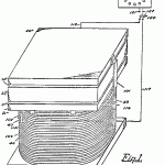
In describing the procedure of carrying out my invention, and the details of the apparatus, in one form of illustration, which form has been fully demonstrated as being capable of intercepting and transferring electric wave energy, reference is now had to the accompanying drawings, in which Figure 1 is an isometric view showing the electric wave interceptor or collector mounted upon the electric transformer, also showing the current distributing connecting wires leading to a rheostat and to a series of incandescent lighting lamps.
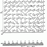
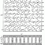
Figure 2 is an inverted plan view of the top or positive plate of the wave interceptor, or collector, showing the series of aerial terminals or contacts and the broken or dead end or open circuit (hereinafter in most cases called “broken circuit”) connections with the contacts.
Figure 2A is a transverse sectional view taken through the collector aerial plate, and the terminal contacts taken on line 2A–2A of Figure 2.
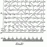
Figure 3 is a plan view of the lower aerial plate of the wave collector, showing the aerial terminal contacts, and the broken circuit connections.
Figure 3A is a transverse sectional view of the lower collector plate and the terminal contacts taken on the line 3A—3A of Figure 3.
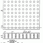
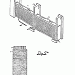
Figure 4 is a perforated member made of insulating material for containing the resistance coils between the, upper and lower aerial plates, showing the top member or cap of each resistance coil of the series.
Figure 4A is a transverse sectional view of the insulating member shown in Figure 4, taken through the series or perforations lowest in position in the member, on the line 4—4 of Figure 4, and shows the resistance coils in full lines.
Figure 5 is an enlarged detail side view of one of the resistance coils which are located in the insulated member shown in Figure 4.
Figure 6 is an end view of one of the resistance coils with the cap removed.
Figure 7 is a diagrammatic view of the electrical connections between the resistance coils mounted between upper and lower aerial plates.
Figure 8 is a transverse vertical sectional view of the complete ether wave collector, taken on the line 8—8 in Figure 7.
Figure 9 is a segmental plan view of the other wave transformer, showing the coil windings.
Figure 9A shows one of the field coils in end elevation.
Figure 10 is a vertical sectional view of the ether wave transformer and the coil windings taken on the line 10—10 of Figure 9.
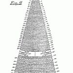
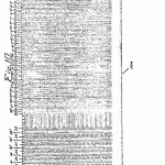
Figures 11 and 11A are diagrammatic views of the two halves of the complete coil windings of the transformer, show- the coil windings, the cores of the windings not being shown, these halves being in separate views to facilitate showing the detail to a larger scale.
Figure 12 is a detail side view of the insulated bridges in the air gap of the transformer, and the reversed field windings, as they appear between the bridges, except where marked “open”.
Referring to Figures 2 and 3, the upper metal plate 20+ and the lower metal plate 21-constitute the aerials of my system of ether wave electric energy collectors, and the terminal contacts 23 on the plate 20+ and the terminal contacts 24* on the plate 21- are shown connected diagrammatically by the electrical conductors of the system.
In the present illustration are shown one hundred terminal contacts, this number corresponding to the number of contacts 23, on the aerial plate 20+, and a corresponding number of terminal contacts 24* on the plate 21-, the terminal contacts or posts 23 and 24* on the respective plates being spaced equal distances from each other in rows of ten contacts in the direction of the length and width of the respective plates, and therefore have corresponding registering positions with each other.
The system of electric wave potential activity in my invention is embodied, in the rapid changes in polarity of broken electric circuits, and such a systematic, arrangement of the broken circuits as will cause the ether wave potential to seek a path of lowest conductivity and not overload any one conductor, and as an example of the operation of the system the current path will be electrically traced, and the transmission of the ether wave potential followed from the source of collection to a definite electric wave energy circuit.
Let 20+ indicate, with its terminal contacts, the positive source of permeability and conductibility of recognized waves of ether, which invariably act from a north to a south pole. To equalize the general dispersion of these recognized waves of ether for the purpose of effecting polarization of the potentials of the ether waves, the ether waves are broken and with the change in direction of the wave potential, an electric potential is produced, and the waves of ether are conducted from contact to contact through a system, of wiring found, by discovery, and demonstrated to be practical in operation, which produces electric energy or electromotive force between the plates 20+ and 21-, and which plates may be compounded or duplicated.
The system of broken electric circuits which provides means of obtaining the wave potential, is embodied in the system of wiring of both plates 20+ and 21-, and in the transmission of electric waves and change in polarity during their transmission from contacts on the plate 20+ to the contacts on the aerial plate 21-, the method of ether wave conductivity being absolutely collective and accumulative, showing that the difference of electrical pressure as discovered in my system is the source of electromotive force between the ether wave collecting plates 20+ and 21-.
The system of wiring of the plate 20+ will now be particularly described. It has been found that fluctuations constantly exist in the collective capacity of the aerial plates 20+ and 21-.
Following the diagram of winding on the inverted top plate 20+ shown in Figure 2, the aerial terminal contacts are numbered in succession, from one to ten, beginning at the right hand end of the lower row, then for the next row from 11 to 20, beginning at the right hand of the plate, and so on to the upper row, which is numbered in the same direction from 91 to 100.
The wire connections on the top plate 20+, Figure 2, are through a conducting wire V, one terminal of which is connected with the contact 1, and the other terminal with the terminal contact 2, and also from the contact 1, by the wire lAo, with contact 12.
Contacts 2 and 13 are similarly connected. A similar connection extends from contact 3 to contact 14. A similar connections are made from contact 3 to contact 4, from 4 to 15, 5 to 6, 5 to 15, 6 to 17, 7 to 8, 7 to 17, 9 to 18, 9 to 20, 10 to 20, 11 to 12, 12 to 23, 13 to 23, 14 to 24, 15 to 16, 16 to 26, 19 to 29, 21 to 22, 22 to 31, 22 to 32, 23 to 24, 23 to 32, 24 to 34, 25 to 26, 25 to 35, 26 to 36, 27 to 37, 27 to 38, 28 to 29, 30 to 39, 32 to 41, 32 to 42, 33 to 34, 33 to 44, 36 to 37, 36 to 47, 38 to 48, 40 to 49, 41 to 52, 42 to 43, 45 to 54, 45 to 56, 46 to 47, 46 to 56, 47 to 57, 50 to 59, 51 to 52, 51 to 61, 52 to 53, 53 to 54, 55
to 64, 55 to 65, 56 to 57, 58 to 69, 60 to 70, 61 to 62, 63 to 64, 64 to 75, 65 to 76, 66 to 67, 66 to 76, 67 to 76, 68 to 77, 68 to 78, 68 to 79, 70 to 79, 71 to 72, 71 to 81, 72 to 81, 73 to 82, 73 to 84, 74 to 83, 74 to 85, 75 to 85, 75 to 86, 76 to 87, 77 to 78, 78 to 88, 78 to 79, 80 to 89, 81 to 91, 82 to 83, 83 to 92, 83 to 94, 84 to 95, 96 to 96, 86 to 97, 87 to 88, 87 to 98, 88 to 89, 88 to 98, 88 to 99, 90 to 99, 99 to 100, 92 to 93, 94 to 95, 95 to 96, 98 to 99.
The lower plate 21-, as seen in Figure 3, includes the upwardly extending terminal contacts precisely the same in number and position as upon the plate 20+, the contacts being numbered in successive order from 1 to 100 reversed as to the same characters on the plate 21-, and beginning with the contact at the lower row of contacts and at the left hand corner of the plate 20+ and indicating said contacts 1-2-3-4 and so on to 10, then beginning at the left and numbering from 11 to 21 and continuing in said order to the upper row which are numbered from 91 to 100.
The wiring system of. plate 21- is in broken circuits, as on the plate 20+, the direction of the wires being traced from the contacts at which the terminals of a broken circuit ends, and which will now be tabulated, the ether wave conducting broken circuit wires being charged from their respective aerial contacts.
The wires are traced on the plate 21-, from terminal contact 1, through a straight wire lAx having one terminal integral with the contact and its other terminal connected directly with the terminal contact 11.
Then through like conducting wires connections are made from contact 2 to contact 3-and from contact 4 to contact 5-, contact 4 to 13, 5 to 6, 5 to 14, 7 to 8, 7 to 16, 8 to 9, 8 to 17, 8 to 18, 9 to 18, 10 to 20, 12 to 13, 13 to 22,13 to 24, 14 to 23, 15 to 24, 15 to 25, 16 to 25, 17 to 26, 18 to 27, 19 to 38, 21 to 22, 24 to 34, 25 to 34, 26 to 35, 26 to 36, 26 to 37, 27 to 28, 28 to 29, 31 to 32, 31 to 41, 33 to 34, 35 to 45, 36 to 37, 37 to 48, 39 to 48, 40 to 50, 41 to 42, 42 to 43, 42 to 51, 43 to 44, 44 to 55, 46 to 47, 46 to 55, 46 to 56, 47 to 57, 48 to 59, 49 to 60, 51 to 62, 52 to 53, 54 to 63, 54 to 65, 56 to 57, 57 to 66, 58 to 68, 59 to 70, 61 to 72, 62 to 73, 63 to 64, 64 to 74, 65 to 66, 65 to 75, 66 to 67, 66 to 76, 67 to 77, 68 to 77, 69 to 80, 71 to 72, 71 to 81, 73 to 74, 73 to 82, 73 to 83, 74 to 84, 75 to 77, 76 to 86, 76 to 87, 78 to 79, 79 to 89, 81 to 82, 82 to 91 83 to 92, 84 to 93, 85 to 96, 85 to 94, 87 to 96, 87 to 97, 88 to 99, 90 to 100, 90 to 99. Where there is no outgoing wire from one to another terminal contact, a broken circuit occurs on both upper and lower plates.
Between the plate 20+ and plate 21- is an insulated member 22Ao composed of a block of fibrous material in which are a series of vertical openings 22Ax, these openings being the same in number as the contacts on the plates 20+ and 21- and in the same vertical positions, so that there is an exact registration of openings and terminal contacts.
In these openings, are the series of transmission resistance coils 25Ax, one of which is shown enlarged, for illustration, in Figures 5 and 6.
These coils are composed severally of a series of straight wires 25*, starting from a group of central wires around, which other wires are wound, to form a body slightly less in circumference than the openings 22′ in the fibre block 22Ao. At the upper ends of the wires 25 is attached a copper metal cap 25″, and at the lower ends a metal cap 25Ao.
Around these wires, beginning close to the top plate 25\ fine insulated wire 26″ is connected at one end to one of the wires 25*, and the other end coiled about the collected wires 25* winding the wire to the right and its terminal secured at its lower end to the same upright wire 25* from which the winding wire started thus forming a resistance coil, its right hand winding of the coil, as seen in Fig. 4A and 5, being upon coils in which a resistance is interposed between the contacts from a north to a south pole transmission of the electric wave potentials, and these coils arranged in the series being positioned, in the fibre block, as seen in Fig. 4A, the change of the polarity of the wave potentials being through the short circuit wires on the plates 20+, 21-, so that wherever the short circuit occurs there is a rapid change of polarity, the activity being greatest in the coils of the least resistance.
Each resistance coil is of a determinate length, and, as seen in Fig. 4A, leaving a space of the approximate distance from the cap plate 25″ upwardly to the line of the upper surface of the insulated member 22Ao co-equal with the posts or terminal contacts 23″ on the aerial plate 20+, and from the line of the cap 25Ao on the lower end of the resistance coils, to the lower surface of the insulated member 22Ao similar spaces are provided, so that when the upper and lower plates are assembled, the posts or contacts 23* on the upper plate 20+ enter the spaces and come into contact with the caps 25″ of the respective resistance’ coils, and the terminal contacts or posts 24* enter the spaces beneath the lower caps 25Ao of the respective resistance coils, and come into contact therewith, as seen in the sectional view in Fig. 8, leaving between said plates and the insulated member, passages 20Ax, 21Ax, for air gaps, respectively.
When thus assembled, the groups of broken circuits of the plate 20+ contain an electric potential opposed to the electric potential contained in the group of broken circuits of the plate 21-. As these electric potentials are waves of impulse from a south to a north pole intensity, and there is a constant polarization and depolarization of the electric ether waves, in other words, a pressure sufficient to cause an electromotive force is discovered in the field of the plates 20+, 21-.
A force existing in space and collected therefrom, is the supreme power residing in the electric potential, in an interrupted path, with a rapid change of potentials, and has been utilized in my invention, and its development is further illustrated in Fig. 7 of the drawings, which show the plates 20+, 21-, in their relative opposite positions, and with the contacts on the respective plates 20+, 21=, in contact with the caps of the respective resistance coils, the plate 20+ being prismatic, showing the posts or terminal contacts on the said plate, and broken, circuits on both plates 20+, 21-, the wire connections on the plate 21-being shown in dotted lines.
Let the resistance coils 25Ax, of the collector, in electrical connection with the contacts 1— 1 on the respective plates 20+, 21-, indicate the lines of force passing from contact to contact, the said plates 20+, 21-, with their contacts being the terminals of serials through which the electric ether is collected. The winding of these coils are all similar and wound so that the flow of the medium around the coils is from the upper terminal of the coil, which is a north pole, and toward the lower terminal or south pole.
The aerials collect and transmit a flow of the ether or wave energy through the conductors from what ever direction the potentials of the ether are collected, and obtain a pressure of sufficient force to effect a movement in the direction of the least resistance from north to south, through the resistance coils 1 to 100, transmitting a flow of the ether medium or wave energy between all of the contacts on the plates 20+, 21-, the flow being governed by the lines of the least resistance, there following two pressures between the north and south poles of the first coil, the pressures being of opposite potentials, and caused by the opposite polarity of the coils, and the electromotive force thus produced between the plates 20+, 21-, is constant, one line of force being broken by a line of force of a different potential, and these forces all tending toward a common polarity, while producing an electromotive force, in the opposing resistances of these opposite wave potentials.
The method of obtaining electric energy as above described, resides in reciprocal lines of force being established by means of such broken circuits and resistances, as are found by practical results to produce an amperage of current or wave energy, and as the action of the collective broken circuits with reversed polarities produce positive electromotive force, the outgoing conductor 101, leading from the aerial terminal contact 91 on the plate 20+ and the outgoing conductor 102 from the aerial terminal contact 100 on the aerial plate 21-, are connected to the outer magnetizing coil windings of the ether wave transformer, and electric energy is thus obtained.
The amperage of the current or electromotive force collected or accumulated by the ether wave collector is of low intensity, and for the purpose of increasing this intensity, so that the electromotive force may be brought up to a commercial standard, this force is collected and regenerated, one factor being supplemented by another, until the electromotive force is built up to the standard of electromotive force required; that is, the principle within the collector (in the collection of the electromotive force) is applied in a larger degree to the ether transformer, the transformer being the adjunct to the collector, one feeding a low potential to the transformer, which increases this potential of the collector to a higher potential, a dependency existing in the ether transformer upon the collector.
This ether wave transformer 103 is designed with a series of outer magnetizing circuits, which are charged by electricity from the collector, which energize series of inner cores to a greater or less magnetic density, the inner cores being insulated by an air gap from the outer magnetic circuit, and electric current being generated in the central coils, the current flowing through the various coils responding upon the reaction in each circuit, which reaction is least in coils 1 to 8 inclusive, Fig. 11 A, and greatest in coils 25 to 32 inclusive.
The formation of these central coils will now be defined with reference to Figs. 9-10-11 and 11A of the drawings, Figs. 11 and 11A being read together, the connections being shown in full lines at the top of the coil, and in dotted lines at the bottom.
With reference to the plan views of the enlarged segmental portions of the coil, in Figs. 9 and 10 of the drawings, respectively, it will be observed that these views show the windings and the vertical wires or cores, while the diagrammatic views 11 and 11A omit these vertical wires, in order to better illustrate the controlling equalizing reactances, by means of which the electric output of the ether wave transformer is increased to the full load required.
All of the windings of the coil 103 are concentric with a central fibre core piece O, at the center of the ether transformer, around which the first series of vertical core wires V or pins, as seen in Figures 9 and 10, are arranged in close order, and around said wires or pins r the first winding 1 is made, beginning at the top surface of the fibre base 104 and winding the wire circuitously to the right, around these vertical wires or pins V, building up the coil to the height of these wires or pins V (sec Figure 9A).
Outside of the winding 1 is placed another row of vertical wires or pins T, around which the coil winding 2 is built up from the fibre base 104, to the height of said wires or pins 1\
Then around said wire coil winding 2 is arranged a series of vertical wires 3″, and around these vertical wires is made another coil winding 3, and thus continued in the same manner from the coil winding 1, to coil winding 32, outside of which winding is the air gap 32\
Against this winding 32 are positioned the angle or bridge plates 32Ao, which are arranged at equal distances apart, in the direction of the circumference of the coil 103-, and are insulated from the coil winding 32-. These series of coil windings, which are the transformer windings, are wound to the right, as seen in Figure 8A. In the air gap, arc located the magnetizing coils arranged with alternate north and south polarity, the air gap being divided in the circumference of the transformer by bridges, spaced equal distances apart, in which spaces are magnetic coils 109, insulated from the bridges, as seen in Figure 12.
The terminal of this magnetizing coil, extends downwardly in the air gap to the bottom and through the next bridge to the right and the coil wound to form a reverse south pole winding’ S-2, which is indicated by the character S-2, the wiring being continued to the right, and in the direction of the upper end of the coil through the next bridge, and another coil formed, indicated by the character N-3, the wiring being so c6ntinued to the right through the next bridge, and in succession between the bridges to a point about one-half the distance circumferentially of the ether transformer; from the first open space mentioned, at which point is seen a space marked “open” —and from the bridge on the far side of this space, a new coil begins, starting from an upper portion of the bridge and forming a right hand coil and the coil next to the bridge reversed. The coils are then
continued between the bridges, until the bridge is reached on the left hand side of the open space first mentioned.
Outside of the air gaps, the excitation coil winding of the ether transformer is placed, the first two coils 33 and 34, being heavy, or of a larger gauge than the preceding windings from 1 to 32.
The vertical core wires outside of the coil 33 are also of increased size, as seen in Fig. 9-. Continuing the winding of the excitation coils in a series of eight windings from 33 to 40 inclusive, it will be observed that the vertical core wires or pins between the respective windings from 37 to 40 are of a large capacity, several times larger in diameter than the pins between the windings from 1 to 32.
The current from the aerial plate 20+ of the collector is conducted through the terminal 101 leading from said plate to a position, as seen in Fig. 11A, and is connected with the coil 39 of the excitation winding of the ether wave transformer. The conductor 102 leading from the collector plate 21- of the ether wave transformer, is connected with the outer coil 40 of the excitation winding of the ether wave transformer.
The coils of the excitation circuits are connected in series as follows: The outer coil 40 is connected by the conductor 40″ with the coil 34, and the coil 39 through the conductor 39″ with the coil 33. The coil 38 is connected by the conductor 38 with the conductor 34. The coil 37 is connected through the conductor 37″ with the magnetic coil 33. The coil 36 is connected through the conductor 36″ with the coil 33, and the coil 35 is connected by the conductor 35″ with the coil windings 34, thereby connecting all of the excitation coil windings from the inner to the outer coil windings 33 to 40 inclusive.
One end of an insulated bus rod 41 is connected with coil 33 of the excitation circuits, and the other end extends above and is connected to coils 1 to 8. Bus rod 42 is connected to coil 34 and extends to the bottom of coils 1 to 8. In a like manner, bus rods 43 and 44, 45 and 46, 47 and 48, are connected to their respective groups of coils, as shown in Figures 11-11A.
Between coils 32 and 33 is provided a space for the poles the ether wave transformer, the said space in this case being separated into twenty-six divisions, although any even number of poles might be used. Each pole space is separated by non-magnetic bridges 32Ao, two of the said spaces lying upon opposite sides of the transformer, and upon opposite sides of a line intersecting with the axis of said transformer, being marked “open”. The other twenty-four pole spaces arc in this case divided into four groups of six each. The first space adjoining one of the spaces marked “open” contains an iron core wound with an excitation winding, as further herein illustrated, the excitation winding being wound to produce magnetic lines of force from north to south, and in the next space to the right there is a similar core wound to produce magnetic lines of force from south to north, and so on in succession, the sixth space having a coil marked S-6, or south-sixth it being premised that these coils are independent of, and insulated from, the bridges and located
as shown in Figure 12, in which one of the bridges adjacent the space marked “open” is shown in detail, comprising a vertical non-magnetic web extending from the line of the top of the ether wave transformer to the insulated base 104 and provided with the flanges 106-and 107, both insulated from the respective coils 32 and 33 on opposite sides of the pole space.
The system of wiring involved in the aforesaid excitation winding in one completed circuit may be electrically defined as the magnetic field excitation and regulation circuit, which can be traced as follows: Beginning with bus coil 33, the bus rod 41 is shown connected to each of the eight terminal contacts marked by the characters PI, P2, P3, P4, P5, P6, P7 and P8, which are connected respectively, to each of the coils one to eight of the ether wave transformer, and the lower terminals of each of these coils are connected in reverse order to contacts marked N, from which points the circuit divides into two paths, one leading through field coils, and one to bus rod 42, which is connected at its outer end to the bus coil 44 from contacts marked PI, P2, P3, P4, P5, P6, P7 and P8, the group of connections 8A2 lead to terminals 8A6 the field excitation windings successively on fields S6, N5, S4, N3, S2 and NA1, from which the winding terminates, and is brought out at the bottom and connected at 8M to a series of eight wires, the group being indicated by the character 8A3 and shown in dotted lines, these eight wires terminated at contacts marked N, from which points the circuit is completed through bus rod 42, to bus coil 34, specifically the insulated field coils to the right of the space marked “open”, and near the bus rod 42, and are connected with the terminal of an electric conducting wire 8A5 (see Figure 12), forming’ in said space a right hand coil N-l, from which the end of tile wire emerges from the lower portion of the coil, and is extended through an insulated opening 111, in the web of the bridge supporting plate 110, —thence extended upwardly within the next space of air gap to the like coil in said space, and through opening at the upper end of said plate, thence to opening in the opposite plate, forming a left hand coil S-2, and so continued downwardly, the winding being to the left, changing the polarity of the coil. At the lower end of plate 110 the end of the wire emerges, and is then extended through an insulated opening in the next bridge supporting like coils, the winding of the coil in the next space being similar in which the windings are wound to the right, and in the next space to the left, and so continued, these coils being designated in Figure 11A as NA1 (north 1), the next SI (south 1). the next NA2, the character numerals 1 to 6 indicating the spaces of the air gap, the last space in the series of six coils being a south pole winding, indicated by reference numerals S-6. In this latter magnetic coil, the wire is extended upwardly as indicated at 8A6, and with said wire is connected the terminal contacts of the group of conducting wires 8A2 leading from the terminal contacts on the inner end of the bus rod 41- hence completing the winding of the divisional six spaces of the twenty four, and from this connection 8A6 the wire is extended through an insulated opening into the first divided space of the next series of six spaces of the air gap, where the end of the wire is given a right hand, winding, and the magnetic coils thence continued as before described.
The connections upon the other portions of the coil are as follows:
Upon the lower side of the generator coil, and upon the same radius as the bus rod 41, is a bus rod 43, which is connected at its outer end with excitation coil 34 of the transformer and its inner end with the respective coils 9-10-11-12-13-14-15 and 16 of the ether transformer. With this bus rod at the points of connection of said rod with the aforesaid coil windings, are connected the terminal contacts of a group NAo, of wires 8A7, which are connected with the end of the wire in the space past which the bus rod 43 extends, and a north pole magnetic winding formed in said space.
The next bus rod 44, above the last space of the divided air gap of the next series of six spaces, is connected with the pole of the magnetic coil winding 33 of the transformer, at one end, and at the other end with the poles of the coils 9 to 16 inclusive. With the bus rod at the points of connection with the respective coils are connected the terminal contacts PI 6 of a series or group of conducting wires 8A5 from 9 to 16 inclusive the outer numerals being connected with the south pole windings in the space of the air gaps below said bus rod.
With the group of terminal contacts NA10, on the bus rod 43, are connected the upper ends of a group of conducting wires 8A8, the upper ends of the wires being extended upwardly, and connected in an inverse order with the group of contacts PI 6. The next bus rod or wire is positioned upon the other half of the ether transformer, and upon the lower side, and indicated by the reference numeral 45. This bus rod is connected at its outer end with the pole windings 34, and at its inner end with the coil windings 17 to 24 inclusive, and with which windings are connected the terminal contacts 20 of a group of eight wires leading to and connected with the north pole magnet winding wire in the space past which the bus rod extends.
The next bus rod 46 is above the top of the transformer, and is connected with the pole of the excitation coil winding 33 of the magnetic circuit of . the transformer, and at its inner end with the series of coils 17 to 24 inclusive, with which bus rod are connected the series of terminal, contacts PA24 of the group of eight wires PA25 leading to and connected with the south pole windings in the sixth space of the divided air gap over which the bus rod 46 extends.
With the terminal contacts NA20 are connected the lower ends of the series of wires NA21, the other, ends being extended upwardly and connected in inverse order with the terminal contacts 24.
The next bus rod 47 is extended beneath the coils of the transformer, the outer end being connected with the pole of the coil 34, and its inner end connected with the eight coil windings 25 to 32 inclusive.
With the bus rod 47, above these coil windings, are connected the terminal contacts of a group of eight wires 22, the other ends being connected with the coil winding in the first space of the air gap, past which the bus rod 47 extends.
The next bus rod 48 extends upon the top of the transformer, and extends over the sixth space of the air gap. In the fourth quarter of the circumference of the transformer, and is connected at its outer end with the pole or the coil 33 of the magnetic circuits, and at its inner ends, with the poles of the eight t coils 25 to 32 inclusive.
With the said bus rod are connected the terminal contacts of a series or group of eight wires PA26 connected with the south pole coil winding in the sixth space aforesaid, and with the contact terminals of the group of wires NA22, are connected the ends of a group of eight wires PA27, their upper ends being connected in reverse order with the terminal contacts of the wires PA26 on the respective coils 32 to 25 respectively.
The description being now completed of the magnetic excitation coil windings, and of the magnetic field coil wire regulation, which latter it will be observed are arranged for the excitation of any portion of the ether transformer, from the magnetic circuit to the coil windings 1 to 32 from the consumption of the current obtaining the full self induction action or current generating capacity of the transformer, the magnetic circuits being traced in like manner as first described.
The ether wave collector, as arranged in conjunction with the ether wave transformer, before described, and for practical operation, is as seen in Fig. 1, the lower plate 21 of the collector resting upon insulating cross bars 113-116 which extend across the top of the transformer 103. In this position of the collector, it will be seen that the current conducting wires are in the form of bars, the upper end of the bar 118 being connected with the plate of the collector, and the lower end extended downwardly and insulated from plate 21 and bent inwardly and thence downwardly into contact with the excitation winding of the outer excitation coil 40 of the magnetic circuits.
The feed wires for current distribution are connected with the coils of the magnetic excitation circuit, like terminal of one wire indicated by the character 117, being connected with the pole of the coil 33 of the transformer 103, opposite the space of the divided air gap marked “open” and first alluded to in the description of the first series of six spaces of the air gap of the transformer.
The other wire 118 has its inner terminal connected with the coil winding 34 of the magnetic field upon the reverse portion of the transformer.
The outer portions of these feed wires 117 and 118 connect with a double pole switch 120, which makes contact with the conducting wires 121-122 of the rheostat controller 124.
With the rheostat are connected the inner terminals of the conducting wires 125 and 126, the outer terminals being connected in parallel with the lamp circuit upon the socket board 127, in, which are shown the incandescent lamps 128 in series, in the incandescent circuit.
It is obvious that the outgoing feed wires may be connected with the fields of a motor and electric energy transmitted at high and low velocity as the load of the motor increases, or vice versa, as the increase in the number of incandescent lamps are increased, to excite the magnetic circuits of the transformer, the efficiency of which will now be described in connection with the collector of ether wave medium.
The electromotive force of the current from the ether wave aerial collector flows or is conducted by the conductors 101 and 102, whose terminals are connected with the aerial plates 20+, 21-, respectively, and also with the coil windings 39 and 40, respectively, of the ether wave transformer. The current flowing in the magnetic circuit of the coils energizes conductors 39″, 40″, magnetizing coil windings 33 and 34 respectively, and these, coils 33 and 34 energize the magnetic coils 37 and 38, through the conductors 37″, 38″ respectively, and the coils 35 and. 36 are energized through the conductors 35″, 36″ respectively, from the coils 33 and 35 respectively, and the whole magnetic circuit from. 33 to 40 arc energized. The current then flows through the bus rods to the coil near the center of the transformer which has the least resistance, which as indicated the first coil outward from the insulated core piece O.
The current generated and flowing through the bus rod is generating an electromagnetic force in the magnetic circuit.
The coil energized has a return through the bus rod 43- to the magnetic circuit to its bus coil 34, and the electromotive lines of force are impeded by changes in the lines of force which cause fluctuations in the change of polarity.
The double pole switch 120 being thrown to bring into contact the outgoing feed wire terminals of the feed wires 117-118, with the conducting wires 121-122 of the rheostatic controller 124, the current of the required force is transmitted by the conductors 125-126 to the series of incandescent lamps 128.
The transformer now in use by myself for service lighting is now connected with a lighting circuit now in operation.
The electromotive force of the transformer being increased, by the amount of load, increases the flow of the current through the first magnetizing coil of the transformer from 1 to 8, setting up new lines of electromotive force, the potentials of which in moving toward the lines of the least resistance, meet a change in lines of force through the reversed group of wires 8M, at the same time generating a larger magnetic electromotive force in a reverse movement by the path of The bus rod 41, which being met by an increase of the lines of magnetic force from the magnetic coils, acts to control the movement of the current, while generating in the collision of these lines of force a higher electromotive force, involving the magnetic coils in the spaces from 1 to 6 inclusive, of the air gap, the current now flowing through the magnetic coil during its flow from the group of conductors 8A3, to the conductors in the space SA6 in the first series of six spaces of the air gap, the current flowing through the magnetic wiring by the conductor 8A5, in the
space marked NA1, thence through the magnetic winding SA2 in the next space, thence through the magnetic windings NA2 in the next space, thence through to magnetic winding SM in the next space, thence through the magnetic winding NA5 in the next space, thence through the magnetic windings NA6 in the next space, at which point, the current whose fluctuations have been regulated in rapid changes of polarity, with increased electromotive force, flows with an inductive force through the bus rod to energize the series of coils from 1 to 8, it being observed that in my transformer the electromotive force is being from magnetizing coil 1 to 32 respectively until an increased load is thrown on the transformer, increasing the magnetic lines of force of the coils of the transformer, when the inductive force is set up in the magnetic circuits through conductors 37″, 35″, involving a generation of current which finds its path through bus rod 44, and bringing into circuit the next 8″ coils of the transformer where the lines of force in the correction of the poles of the group of wires 8A1 are subjected to a change of polarization and depolarization through one or more of the wires 8A8, setting up additional electromotive force, its fluctuations being made constant through the magnetic field coils in the spaces of the air gap from 1 to 6 in the next quarter division of the transformer, and as the load further increases so as to involve the magnetic circuits 33 and 35, the flow of the current is inducted through the conductors 35Ax, 36″, through the bus rod 46, taking the electromagnetic force from the excitation from all the coils of the transformer, whose potentials follow the group of conductors which lead to the next series of coil windings 16 to 24, flowing through the reversely connected group of wires NA21, and is then conducted through the series of magnetic coils in the next series of coils respectively.
As the load increases, the Principal magnetic coils shown in heavy lines in Figs. 11-11A in the last distribution of current, flows from the dense coil 32, energizing bus rod 48, and also energizing the series of eight coils of the transformer from 1 to 32 inclusive, the current flowing through the reversely connected conductors P27 through magnetizing field coils, cutting the line of force and creating an electromotive force the current flowing through the fourth division of the six spaces of the air gap, and the magnetizing field coils in said series, in which the fluctuations of the current are made constant and the full distribution of the current is now attained from each portion of the transformer, in which portions, while the electromotive force is increased to meet the demands of the load, a constant regulation is being effected in the excitation coils and through the magnetizing field coils, impeding the lines of least resistance which are afforded a compensating resistance in proportion to the load cut in and out through the rheostatic controller, hence, as the electromagnetic force of the transformer is increased to supply the electromotive force required, the accumulation of the ether waves in the collector produces an electromotive force of undiminished quantity, this result being a new discovery of far reaching benefit to mankind, involving as it does the inceptive potency of electric energy for all, purposes, evolved from the general ether wave field of electric medium by me.
Having fully described my invention, what I now claim as new and desire to secure by Letters Patent, is:
The production and generation of an electromotive force from the accumulation of the ether waves of an unknown potential, from the general field of ether wave electric medium.
The production and generation of an electromotive force, from the accumulation of the potentials of ether waves of electric medium, and their polarization into electromotive force constant.
A source of electromotive force, comprising an inductive polarization and depolarization of the pulsating waves of ether, from the ether wave potential of the ether wave electric medium.
The production and generation of an electromotive force, consisting of the accumulation of the ether waves of the general electric ether wave medium, and changing their potentials in the paths of broken circuits of opposite polarity, and polarizing and depolarizing the wave potentials and subjecting the energized potentials to a transmission through magnetic circuits.
A source of electric motive force, comprising the inductive ether wave potentials of the ether wave medium, whose potentials are changed through resistances in their paths, and then polarized and depolarized in transmission.
The method described of producing an electromotive force, consisting in collecting the ether waves from the general field of electric medium, their potentials changing within broken circuits, then through polarized resistances.
The method described of producing an electromotive force, consisting in collecting the ether waves from the general field of electric medium, changing their potentials, transmitting them within broken circuits, polarizing and depolarizing the potentials and through polarized resistances in magnetic circuits.
The method herein described of producing an electromotive force, consisting in collecting and accumulating the ether waves from the general field of electric ether wave medium, changing their potentials and transmitting these potentials within broken circuits, polarizing and depolarizing these potentials in a transmission through polarized resistances in magnetic circuits of reversing polarities.
The method herein described of producing an electromotive force constant, consisting in collecting and accumulating the ether waves from the general field of electric ether wave medium, changing their potentials and transmitting these potentials within paths of broken circuits, changing their potentials and polarizing and depolarizing these potentials and transmitting them through polarized resistances, thence through magnetic circuits in which circuits the polarities are changed according to the electromotive force.
The method and apparatus herein described, for collecting from the general ether field, of electric medium, of electric ether waves or ether in an accumulative, distributable, measurable, electromotive force.
The method, and apparatus herein described, for collecting from the general ether field of electric medium of the ‘wave potentials, and breaking up the lines of force of these potentials to produce an electromotive force.
The method and apparatus herein described for collecting and accumulating from the general field of electric medium of ether waves of unknown polarity and converting these waves into lines of electromotive force of constant polarity.
The method and apparatus herein described for collecting and accumulating from the general field of electric medium, of ether waves of unknown polarity from aerials of opposite polarity, transmitting these waves through broken conductors in groups of broken circuits in electrical contact with the aerials, then through polarized resistances in electrical contact with the conductors in the broken circuits.
The method and apparatus herein described for collecting and accumulating from the general ether field of electric medium of the ether waves, consisting in establishing a conductivity of the wave medium between aerial conductors in parallel, and conducting the ether wave from conductors through groups of broken circuits in electric connection with the terminals of the aerials, and interposing polarized resistances between the terminals of the aerial conductors.
The method and apparatus herein described for collecting and accumulating from the general ether field of electric medium of unknown polarity, of ether waves of electromotive force, consisting in conducting the lines of force of the ether electric waves through aerials and within groups of broken circuits, and breaking up the lines of force, then reversing the polarity of these potentials through the medium of polarized resistances.
The method and apparatus herein described for collecting and accumulating from the general ether field of electric medium, of an amperage of electromotive force, and increasing its lines of force in a transformer of magnetic lines of force.
A collector of ether electric waves, consisting of aerial conductors, and a group or groups of wave polarizing and depolarizing broken circuits leading therefrom, and polarized resistances so related to the broken circuits as to break up the potentials of the ether medium.
A collector of ether electric waves, consisting of aerial conductors, and a group or groups of wave polarizing and depolarizing broken circuits in wave transmitting connection with the terminals of the aerial conductors, and polarized resistances in the path of the electric medium at the terminals of the aerials.
A collector of the ether electric waves, consisting of aerial conductors, and terminal contacts and broken wave group or groups of conductors polarizing and depolarizing connected with the terminal contacts.
A collector of ether electric waves, consisting of aerial conductors of the potentials of the electric waves, and opposing group or groups of wave polarizing and depolarizing broken conductors, in wave transmitting connection with the terminals of the aerial conductors, and polarized resistances connecting the group or groups of broken circuits and insulated therefrom.
A collector and accumulator of the ether electric waves, consisting of wave inductive aerial plates, and terminal contacts in opposite wave transmitting positions.
A collector and accumulator of the ether electric waves, consisting of wave inductive aerial plates, each plate having a series of terminal contacts in registering positions, and polarizing and depolarizing conductors in broken circuits carried by the terminal contacts on each plate, and wave transmitting polarized resistances connecting the registering contacts.
A collector and accumulator of the ether electric waves, consisting of separate wave inductive aerial plates, and a series of terminal contacts on each plate in registering positions to each other respectively, means for insulating one plate from the other, and a group or groups of conductors in broken circuits on each plate, in wave transmitting connection with the terminal contacts, and polarized resistances connecting the contact on the other plate.
A collector and accumulator of the ether electric waves, consisting of separate wave inductive aerial plates, and a series of terminal contacts on each plate, an insulating member between the said plates provided with openings registering with and admitting said terminal contacts, polarized resistance coils in said openings connected with the respective contacts on the separate plates, and wave polarizing group or groups of broken conductors on said terminal contacts.
An apparatus for the collecting, accumulating and accreting, the ether electric wave energy, comprising inductors of the ether electric waves, circuit breaking polarizers and depolarizers of the electric waves, potentials changing elements connecting the broken circuits, and magnetic circuits, and polarizing and depolarizing current transmitters in the magnetic circuits.
A collector and accumulator of the ether electric waves, and a transformer of increased energy of electromotive force, from the amperage of wave energy transmitted from the accumulator.
An ether wave transformer of electromotive force, comprising magnetic circuits, and polarizing and depolarizing circuits controlling the magnetic circuits.
An ether wave transformer of electromotive force, and magnetic circuits of increased activity without the main body, and an air gap between, and polarizing and depolarizing circuits connecting the poles of the magnetic circuits of the main body, with the poles of the magnetic circuits of the outer body, and electrically controlled thereby.
A collector and accumulator of the ether electric waves, and magnetic circuits energized by the polarized and depolarized ether waves from the accumulator.
An ether wave transformer of electromotive force, comprising an internal body of magnetic circuits, and an external body of magnetic circuits of increased magnetic intensity to that of the internal body, and an air gap between, conductors connecting the magnetic poles of the terminal body with the magnetic poles of the outer body, and groups of polarizing and depolarizing circuits connecting the conductors of these poles with each other, and polarized, resistances in the air gap connected with the polarizing and depolarizing circuits.
An ether wave transformer of electromotive force, comprising a series of internal magnetic circuits, and a series of external magnetic circuits, and an air gap between, conductors connecting the poles of the external magnetic circuits with the poles of the internal magnetic circuits in progressive degrees of electric induction, and polarizing and depolarizing circuits connected with the terminal contacts of the conductors with the poles of the magnetic internal circuits with each other in reverse order, and conductors leading from said poles to the air gap and polarized resistances connected with the polarizing and depolarizing circuits within the air gap.
32. An ether wave transformer of electromotive force, comprising an internal body of magnetic circuits, and an external body of increased magnetic intensity, to the internal
body, and having an air gap between, insulated means connecting the internal and external bodies of magnetic circuits, and conductors connecting the poles of the internal and external magnetic circuits in progressive degrees of electric induction, and polarizing and depolarizing circuits connecting the conductors from the poles of the magnetic circuits in series, and series of polarizing and depolarizing circuits connecting said series of conductors in reverse order, and polarized resistance coils in the air gap insulated from the magnetic circuits and connecting electrically the series of reversed polarizing and depolarizing circuit from the magnetic circuits.
The herein described method of producing electromotive force between the poles of a transmission resistance coil.
The herein described method of producing electromotive force from the ether waves of electric medium between the lines of force passing through the poles of a transmission resistance coil.
The herein described method of producing electromotive force from the aerials of conductors of ether wave electric medium, by changing their potentials during the transmission of the lines of force through wave transmission resistances.
The herein described method of producing electromotive force conducted through the aerials of the ether wave electric medium consisting in changing their potentials through broken conductors in contact with the aerials and during transmission of the lines of force through wave transmission resistance coils.
In witness whereof I hereunto affix my signature: HARRY E. PERRIGO

