Inventor: Edwin V. Gray, Sr.
Primary Examiner: Jeffrey Sterrett
Current U.S. Classification: 363/33; 323/207; 323/228; 323/291; 363/94; 363/110
International Classification: H02M 342
Patent number: 4595975
Filing date: Oct 18, 1984
Issue date: Jun 17, 1986
Claims
- An electrical driving system comprising:
- a source of electrical voltage;
- a vibrator connected to said source for forming a pulsating signal;
- a transformer connected to said vibrator for receiving said pulsating signal;
- a rectifier connected to said transformer having a high-voltage pulse output;
- a capacitor for receiving said voltage pulse output;
- a conversion switching element tube having first and second anodes, electrically conductive means for receiving a charge positioned about said second anode and an output terminal connected to said charge receiving means, said second anode being connected to said capacitor;
- a commutator connected to said source of electrical voltage and to said first anode; and
- an inductive load connected to said output terminal whereby a high energy discharge between said first and second anodes is transferred to said charge receiving means and then to said inductive load.
- A system as claimed in claim 1, including
- a second capacitor for receiving a charge frcm said load.
- A system as claimed in claim 2, including
- a switching element tube positioned in series between said commutator and said first anode.
- A system as claimed in claim 3, including
- a second source of voltage and a switch for receiving a signal from said second capacitor.
- A system as claimed in claim 4 wherein:
- said conversion switching element tube includes a resistive element in series with said first anode; and
- said charge receiving means is tubularly shaped.
- A system as in claim 1 wherein said source comprises a direct current source and wherein said system further comprises:
- a source of alternating current; and
- a switch means for selecting said direct-current or said alternating-current power source as input to said rectifier.
- A system as in claim 1 wherein said rectifier comprises a bridge-type rectifier.
- A method for providing power to an inductive load comprising the steps of
- providing a voltage source;
- pulsating a signal from said source;
- increasing the voltage of said signal;
- rectifying said signal;
- storing and increasing said signal;
- conducting said signal to a high-voltage anode;
- providing a low-voltage to a second anode to form a high energy discharge;
- electrostatically coupling said discharge to a charge receiving element;
- conducting said discharge to an inductive load;
- coupling a second capacitor to said load; and
- coupling said capacitor to said source.
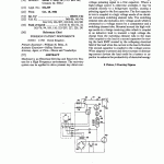
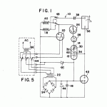
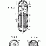
Disclosed is an Electrical Driving and Recovery System for a High Frequency environment. The recovery system can be applied to drive present day direct-current or alternating-current loads for better efficiency. It has a low-voltage source coupled to a vibrator, a transformer and a bridge-type rectifier to provide a high voltage pulsating signal to a first capacitor. Where a high-voltage source is otherwise available, it may be coupled directly to a bridge-type rectifier, causing a pulsating signal to the first capacitor. The first capacitor in turn is coupled to a high voltage anode of an electrical conversion switching element tube. The switching element tube also includes a low voltage anode which is connected to a voltage source by a commutator and a switching element tube. Mounted around the high voltage anode is a charge receiving plate which is coupled to an inductive load to transmit a high voltage discharge from the switching element tube to the load. Also coupled to the load is a second capacitor for storing the back EMF created by the collapsing electrical field of the load when the current to the load is blocked. The second capacitor is coupled to the voltage source. When adapted to present day direct-current or alternating-current devices the load could be a battery or capacitor to enhance the productivity of electrical energy.

