Designed by: Kim Zorzi | January 31, 2005
So our goal here is to design a new aircraft that does not run on the usual combustion technology. But on the energy of the wind, by producing stable vortices that can produce lift from the centrifugal acceleration of air.
Thru the use of Pyromagnetics, the creation of a powerful magnetic field is brought about to create a Thermodynamic Air Compressor whereas this high pressure air is funneled to a vortex chamber to create a powerful tornadic effect. Which in turn can create thrust thru suction?
By mating two concepts, Thermomagnetics and thermodynamic cycling of circulating air masses creates a new engine concept with unbelievable power. Creating power thru the use of vacuum instead of the use of standard combustion technology.
HOW IT WORKS
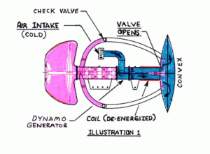
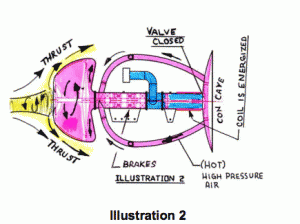
The first step into designing a convective thermal component aircraft engine is to decide how to cycle the thermal current into a tappable reservoir. One method is to expel heated air from a plenum chamber that has the ability to compress it for a propulsive effect. The expelled air is then expelled up into the vortex chamber to produce a rotating swirl that acquires angular momentum which then exits over the diffuser in the center whereas it reverses direction caused by the Coanda Effect and is ejected into the ambient fluid.(Illustration 2 shows this better)
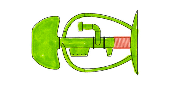
In the above illustration we see the air intake, the air intake plenum throat, and the pyromagnetic compressor (Blue).
Pyromagnetics, sometimes called Thermomagnetics is the changing of the magnetic properties of a material with temperature. Thermal differences generated by the atmosphere by the sun might provide the energy to establish pyromagnetic oscillations in large plates. The oscillating plates might then be used to compress and or direct air to propel large lightweight aircraft to the upper limits of our atmosphere. 600,000 ft. (120 miles) or more.
Based on the Tesla Patent 396,121 filed Jan. 15, 1889 “Thermal Magnetic Motor”
The operation of the Pyromagnetic engine concept is as follows. When an electromagnet with a hollow iron core is activated, it attracts a thin steel plate diaphragm to compress air forcing it into ducts for rapid expulsion. The rapid compression heats the air which in turns heats the plate and the end of the electromagnetic core, causing them to demagnetize. The compressor plate is then released and forced away from the core by a strong counter-spring. As the plate moves away expanding the chamber, the air is again sucked into the air intake plenum throat of the magnet re-establishing airflow. The cool intake air is further cooled as it expands to fill the chamber. The plate’s distortion is concave during compression and convex during expansion. The differential heating effect further assists the demagnetization and cooling processes. This external heating and cooling occurs naturally in synchronization with the compression and expansion cycle. The compressor plate and core magnet tip heat most during the concave phase, and cool most during the convex phase. This allows are two thermal components, rising and falling air to power our pyromagnetic aircraft engine directly.
The steel plate that cuts a magnetic field is a natural Faraday homopolar dynamo and it can be used to magnetize the intakes hollow magnetic core. Therefore, if a pyromagnetic compressor is allowed to spin by exhaust vectoring it will itself be a natural dynamo, as it jets air at an angle out of the rim exhaust holes. Current only needs to be drawn off the rim and grounded at the center.
The intake throat houses a generator. The generator output from the intake turbine directly couples to the primary coil producing the magnetic field for the core of the magnetic tube. If the magnetic tube’s core and backflow valve are closed, the intake turbine will slow down. This will lower the magnetic field current and further allow the compression plate to spring away. The turbine will then experience maximum induced flow and re-magnetize the primary magnetic core. Thus it is very important that the core magnet be slaved to its input or output and not to a lab power supply. The cycles achieve an endless magnetization and de-magnetization that happens up to 8 times a second.
As the air is compressed from the convex plenum chamber it is pumped into the Vortex Thruster Chamber (Pink color) whereas the second phase of our operation now takes place.
Vortex Thruster Chamber
The basic working principle is to create a strong swirling flow to produce very low pressure above a lifting surface, which generates thrust. Swirl in the incoming flow is achieved via an open vortex chamber, and the resulting low pressure rarefaction is intensified by an airfoil-shaped diffuser, which ensures an attached flow without separation. The flow enters the swirler, acquires angular momentum and exits over the diffuser, where it reverses direction (by the Coanda effect) and is ejected into the ambient fluid. Such a flow is like an artificial tornado, creating a strong rarefaction (low pressure) zone on the upward-facing, internal top surface of the vortex chamber. Since there is higher ambient pressure on the external bottom surface of the chamber, a lift force is generated by this pressure difference. Additional rarefaction is created by the flow over the upper surface of the diffuser by its airfoil shape. Operating parameters for the vortex chamber must be determined to avoid separation over the diffuser. Such attached flow over the diffuser is possible since the Coanda effect is much stronger in the presence of swirl and is also stronger in turbulent flows.
Physically, the difference between conventional jet propulsion and our vortex thruster is that in the former, the net force generated and the power requirements are determined by the same axial velocity component. In our vortex thruster, a large net force is generated primarily by the tangential velocity component, but only a relatively small axial flow rate, and hence, relatively small power is required.
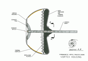
The Thruster housing incorporates a input turbine blade in the bottom of the intake throat. This high pressure air as it passes thru the throat encounters a specially designed turbine blade that will spin the Repulsion plates to a high RPM. Hot Air is funneled into the housing from the pyromagnetic compressor and rotated to the outside diameter of the inside of the housing thus creating a high pressure area inside the housing. A resulting tornadic flow of air starts to pressurize the housing and the outflow will also spin the exhaust turbine at the front of the housing, resulting also in a backflow of torque to the repulsion plates and input turbine. As the temperature differential starts to occur inside the housing and the repulsion waveplates reach subsonic speed, then the resulting effect ignites the repulsion effect as previously discussed in other material.
Technical Approach of the Votex Thruster Housing
Rotating flows within vortex chambers have been investigated extensively. The tangential entry of fluid into a typical cylindrical vortex chamber, via the guiding vanes around the periphery, causes swirling motion of the fluid (mixture). In the core region of the flow away from the walls, the radial pressure gradient balances the centrifugal force; this is the so-called cyclostrophic balance. Near the end walls, the centrifugal acceleration is very small due to the boundary layer effect, but the radial pressure gradient is essentially the same as in the core region. Thus, the lack of cyclostrophic balance causes the pressure gradient to generate a secondary flow towards the axis along the end walls, balanced by the frictional force. This leads to an end-wall boundary layer with a substantial inflow radial speed vr , the maximum of vr (and of axial and azimuthal velocities) occurring inside the boundary layer. This inflow of the rotating fluid along the end wall prevents the typically desirable prolonged retention of small particles within the chamber, because they are carried away by the fluid flow along the axis. At practical operating speeds, the flow in the near-axis region is extremely complex, involving very high turbulence and sound-producing axial oscillations. A detailed study of the flow patterns in this and other regions of the vortex chamber for various operating parameters is necessary in order to develop more efficient designs.
Experimental and theoretical studies show that rotating flows possess three fundamental features, described below.
High centrifugal force: Typical inlet gas velocities (~100 m/s) into a chamber of radius ~ 0.1m produce a centrifugal acceleration ac ~ 10 4 g. This high centrifugal force is central to all applications discussed here, and ensures stability of the central cavity and motion of solid particles/fluid bubbles in circular trajectories inside the cylindrical vortex chamber.
Near-axis flow: Near the axis of rotation, if the speed is high enough, a gaseous cavity is formed when a liquid is used as the working fluid, and a recirculating zone (such as vortex breakdown bubble or internal separation, i.e. separation away from any wall), forms if the fluid is a gas. The complex flow pattern in this region depends on the operating conditions (such as Reynolds number and Rossby number) and the chamber end-wall profile, and it considerably influences the flow in the rest of the chamber. A clear understanding of this region based on rigorous hydrodynamic analysis is essential for optimal design of these machines, particularly the vortex engine and vortex thruster.
Bistability: When two-phase flow is involved, our experiments in vortex chambers have shown the existence of two stable states, either condensed or rarefied.
Condensed stable state: At high particles concentrations, the denser medium (solid or liquid) forms a tightly packed layer near the periphery of the vortex chamber and provides a very large interface area between the two media.
- Rarefied stable state: At lower concentrations, the particles are distributed homogeneously and move in circular orbits in the lighter fluid medium. The radii of the orbits depend on the particle size.
SUMMARY
Physically, the difference between conventional jet propulsion and the Vortex Thruster Engine is that in the former, the net force generated and the power requirements are determined by the same axial velocity component. In the vortex thruster, a large net force is generated primarily by the tangential velocity component, but only a relatively small axial flow rate, and hence, relatively small power is required. Preliminary experiments using a simple device to model a thruster have verified that thrust is in fact generated in the same direction as the exit flow. The initial conservative estimates indicate that a thruster with a 1 sq. m. chamber area can generate 4 tons of thrust with 17 times less energy than a conventional jet. The size of this engine should generate (16” Dia) should generate 1400 lbs of thrust and weigh in at a mere 60 lbs. This equates into a aircraft engine with a power to weigh ratio of 0.0428 . In comparison, a Rotax 912 weighs 125 lbs and produces 90 H.P. which equals to1.38. Nasa’s standard for aircraft engines is under 2.0.
The vortex thruster has significant applications enhancing or replacing conventional thrust/lift devices, e.g. propellers and wings on helicopters, aircraft, and ships; in particular, a bladeless helicopter will be highly desirable innovation from the viewpoint of maneuverability and safety. The main idea behind this device is completely new — based on the “artificial tornado” principle.
Designer Kim Zorzi expected that a Vertical Vortex Thruster Engine-based “helicopter” would be very simple, compact and much more efficient than a conventional helicopter. Fuel requirement is non oil related and gets its power from electricity generated by differentiated air temperatures.
These vortex machines have the potential to substantially increase energy savings such as petroleum, chemical, power transportation, pharmaceutical, electronics, environmental and agriculture, amounting to hundreds of millions of dollars per year in each state alone.


